Five-Axis Machining Centers: From CAD Model to Finished Part
Modern manufacturing increasingly requires complex components with curved surfaces, angled features, deep cavities, and tight dimensional requirements.
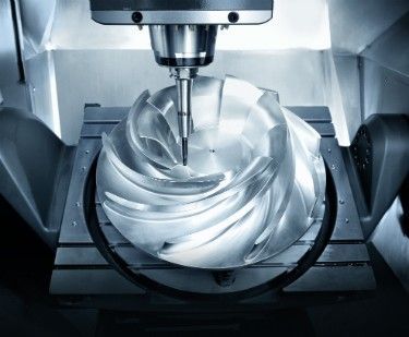
Five-Axis Machining Centers provide coordinated movement across three linear axes and two rotational axes, allowing cutting tools to approach a workpiece from multiple directions during a machining operation.
Compared with conventional three-axis machining, five-axis technology can reduce the number of setups required for complex components. It can also improve tool accessibility, support more efficient machining of contoured surfaces, and simplify production of geometrically demanding parts.
What Are Five-Axis Machining Centers?
Five-Axis Machining Centers are CNC machine tools capable of controlling five axes of movement simultaneously or through coordinated positioning.
The three primary linear axes are:
- X-axis: Horizontal movement
- Y-axis: Crosswise movement
- Z-axis: Vertical movement
The additional two axes are rotary axes. Their configuration depends on the machine design and may rotate the workpiece, the cutting tool, or both.
This combination allows the cutting tool to maintain different orientations relative to the workpiece.
From CAD Model to Finished Part
A five-axis machining process typically begins with a digital component design and ends with an inspected precision-machined part.
1. CAD Model Preparation
Production begins with a computer-aided design, or CAD, model.
The model defines the geometry, dimensions, surfaces, holes, pockets, contours, and other features that must be manufactured.
Complex components can contain curved surfaces that would require multiple setups on conventional machines. Five-axis machining can approach these surfaces from changing tool orientations.
2. CAM Programming
The CAD model is transferred into computer-aided manufacturing software.
CAM software generates toolpaths based on:
- Part geometry
- Cutting tools
- Machine configuration
- Workholding
- Cutting parameters
- Material
- Required surface quality
Five-axis CAM programming must account for tool orientation and machine kinematics in addition to conventional X, Y, and Z movements.
3. Machine Setup
The workpiece is secured using an appropriate fixture or workholding system.
Because five-axis machines can access multiple sides of a component, fewer setups may be necessary for certain parts.
Accurate workholding remains important because the machine must maintain the required relationship between the workpiece and cutting tool.
4. Tool Selection
Cutting tools are selected according to the material, geometry, operation, and desired surface finish.
Common tools include:
- End mills
- Ball-nose cutters
- Face mills
- Drills
- Reamers
- Specialty profile cutters
Five-axis machining can maintain favorable tool orientations that improve access to curved surfaces and deep features.
5. Multi-Axis Motion
The machine coordinates its linear and rotary axes according to the programmed toolpath.
Instead of keeping the tool perpendicular to a single plane, the machine can continuously adjust its orientation.
This is particularly useful for:
- Complex contours
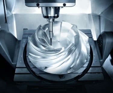
- Impellers
- Turbine components
- Aerospace structures
- Molds and dies
- Medical components
- Blades
- Sculptured surfaces
6. Cutting and Material Removal
The cutting tool removes material according to the programmed path.
Five-axis positioning can reduce the need to repeatedly stop the machine and reposition the workpiece.
Continuous tool orientation can also allow the cutting tool to maintain a more suitable contact angle with the workpiece.
7. Inspection
After machining, the component can be inspected using dimensional measurement equipment.
Inspection may include:
- Coordinate measuring machines
- Touch probes
- Laser measurement
- Optical inspection
- Surface measurement equipment
Some machining centers also incorporate in-process probing to verify workpiece position and selected dimensions during production.
Major Types of Five-Axis Machining Centers
Five-axis machines can be classified according to how the rotary axes are arranged.
| Machine Configuration | Rotary Motion | Typical Characteristic |
|---|---|---|
| Trunnion table | Workpiece rotates/tilts | Strong workpiece positioning |
| Swivel-head | Tool head rotates | Suitable for larger workpieces |
| Tilt-table | Table provides rotary movement | Flexible multi-sided machining |
| Swivel-head and table | Both provide rotary movement | Broad machining flexibility |
| Dual rotary table | Workpiece has two rotary axes | Complex positioning applications |
Trunnion-Style Five-Axis Machines
Trunnion machines use a rotating and tilting table to position the workpiece.
This configuration can provide strong accessibility to multiple surfaces while keeping the cutting head relatively stable.
Trunnion designs are commonly considered for smaller or medium-sized components that can be mounted on a rotary table.
Swivel-Head Five-Axis Machines
Swivel-head machines use rotary movement in the spindle head.
The workpiece can remain relatively stationary while the cutting tool changes orientation.
This configuration can be useful for larger components that would be difficult to rotate on a table.
Table-and-Head Configurations
Some machines distribute rotary movement between the table and spindle head.
This arrangement can provide a wide range of tool orientations and workpiece positioning options.
The exact kinematic arrangement affects programming, machine envelope, workholding, and achievable cutting angles.
Advantages of Five-Axis Machining Centers
Fewer Setups
A complex component can often be machined from multiple directions without removing it from the fixture.
Improved Tool Accessibility
Rotary movement allows the cutting tool to reach surfaces that may be difficult to access using three-axis equipment.
Complex Geometry
Five-axis technology is particularly useful for contoured and freeform surfaces.
Better Surface Quality
Maintaining an appropriate tool orientation can help produce more consistent cutting conditions across complex surfaces.
Reduced Repositioning
Fewer manual workpiece repositioning operations can help reduce setup-related variation.
Efficient Complex-Part Production
Five-axis machining can consolidate multiple operations into fewer setups for appropriate component designs.
Five-Axis vs. Three-Axis Machining
| Factor | Three-Axis Machining | Five-Axis Machining |
|---|---|---|
| Linear axes | 3 | 3 |
| Rotary axes | None | 2 |
| Complex surface access | Limited | High |
| Typical setups | More for complex parts | Often fewer |
| Tool orientation | More restricted | Continuously adjustable |
| Programming | Relatively simpler | More advanced |
| Machine complexity | Lower | Higher |
| Complex component capability | Moderate | High |
Five-axis technology does not replace three-axis machining for every application. Simpler components may not require additional rotary capabilities.
Materials Machined on Five-Axis Equipment
Five-axis machines can process many engineering materials when appropriate tooling and cutting parameters are used.
Examples include:
- Aluminum alloys
- Titanium alloys
- Stainless steels
- Nickel-based alloys
- Tool steels
- Engineering plastics
- Composite materials
Material properties influence spindle speed, feed rate, cutting depth, tooling, coolant strategy, and toolpath design.
Tool Orientation and Machining Accuracy
One of the major benefits of five-axis machining is the ability to continuously adjust tool orientation.
The tool can be tilted relative to a surface to improve cutting conditions and reduce interference between the tool holder and workpiece.
Proper tool orientation can help:
- Improve surface contact
- Reduce tool interference
- Maintain effective cutting geometry
- Reach difficult surfaces
- Reduce unnecessary tool extensions
However, accuracy depends on more than axis count. Machine calibration, thermal stability, mechanical condition, tooling, programming, and workholding also influence final results.
Five-Axis CNC Control Systems
The CNC controller coordinates movement across the machine's linear and rotary axes.
Advanced controllers can calculate coordinated movements while maintaining the programmed relationship between the tool and workpiece.
Important CNC capabilities can include:
- Multi-axis interpolation
- Tool-center-point control
- Collision avoidance functions
- Toolpath compensation
- High-speed machining functions
- Machine simulation
- Automated probing
Automation in Five-Axis Machining
Automation can extend five-axis machining beyond the machine tool itself.
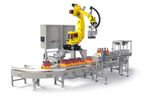
Production cells may integrate:
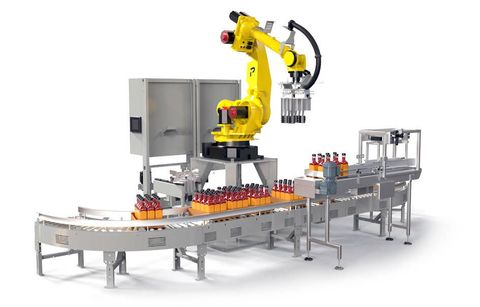
- Robotic loading
- Automated tool changing
- Pallet systems
- Workpiece probing
- Tool measurement
- Automated inspection
- Production monitoring
- Digital job management
For higher-volume production, automated material handling can reduce interruptions between machining cycles.
How to Select Five-Axis Machining Centers
Choosing a five-axis machine requires evaluation of the part, material, production volume, and required machining operations.
Workpiece Size
The machine's work envelope must accommodate the largest intended component while providing adequate clearance for tooling and rotary movement.
Axis Configuration
The arrangement of rotary axes affects accessibility, programming, workholding, and machine behavior.
Spindle Performance
Spindle speed, power, torque, and taper influence the range of machining operations that can be performed.
Accuracy and Repeatability
Machine accuracy and repeatability should correspond to the dimensional requirements of the components.
Control System
The CNC controller should support the required multi-axis toolpaths and programming functions.
Workholding
Fixtures must secure the component while leaving sufficient access for multi-axis machining.
Five-Axis Machining Center Comparison
| Selection Factor | What to Evaluate |
|---|---|
| Machine configuration | Trunnion, swivel-head, or combined |
| Work envelope | Maximum part dimensions |
| Rotary range | Available angular movement |
| Spindle | Speed, power, and torque |
| CNC control | Multi-axis programming capability |
| Accuracy | Positioning and machining accuracy |
| Automation | Pallets, robots, probing |
| Tool capacity | Number and type of tools |
| Workholding | Fixture compatibility |
| Material capability | Supported workpiece materials |
Applications of Five-Axis Machining Centers
Aerospace Components
Five-axis machines can produce turbine components, structural parts, engine components, and complex aerodynamic surfaces.
Automotive Components
Applications include molds, prototypes, specialized powertrain components, and complex tooling.
Medical Components
Five-axis machining can support production of selected orthopedic, surgical, and other precision components.
Energy Equipment
Turbine blades, impellers, pump components, and other complex energy-sector parts can benefit from multi-axis machining.
Mold and Die Manufacturing
Complex cavities and contoured surfaces can be machined with fewer workpiece repositioning operations.
Maintenance Best Practices
Check Rotary-Axis Accuracy
Rotary axes should be inspected and calibrated according to established maintenance procedures.
Monitor Spindle Condition
Spindle vibration, temperature, bearings, and toolholding components should be monitored.
Inspect Tooling
Worn or damaged cutting tools can affect dimensional accuracy and surface quality.
Maintain Coolant Systems
Coolant condition, filtration, concentration, and flow should be maintained according to process requirements.
Verify Machine Geometry
Periodic geometric checks can identify changes in machine alignment or positioning performance.
Frequently Asked Questions
What are Five-Axis Machining Centers?
Five-Axis Machining Centers are CNC machine tools that coordinate three linear axes with two rotary axes to machine complex components from multiple orientations.
What is the main advantage of five-axis machining?
A major advantage is the ability to access complex surfaces and features from different directions while potentially reducing the number of workpiece setups.
What is the difference between three-axis and five-axis machining?
Three-axis machines primarily move along X, Y, and Z axes, while five-axis machines add two rotary axes that allow the tool or workpiece to change orientation.
What industries use five-axis machining centers?
Aerospace, automotive, medical, energy, mold and die, precision engineering, and other industries use five-axis machining for appropriate complex components.
Does five-axis machining require special software?
Five-axis machining generally requires CAM software and CNC controls capable of generating and executing coordinated multi-axis toolpaths.
Conclusion
Five-Axis Machining Centers provide advanced CNC capabilities for producing components with complex surfaces, angled features, deep cavities, and demanding geometries. By combining three linear axes with two rotary axes, these machines can approach workpieces from multiple directions while reducing the need for repeated repositioning.
The workflow begins with a CAD model and continues through CAM programming, machine setup, tooling, coordinated multi-axis cutting, and inspection. Machine configuration, spindle performance, CNC control, workholding, accuracy, and automation capabilities all influence the suitability of a five-axis system.
Five-axis machining is particularly valuable for aerospace, medical, energy, automotive, mold, and other applications involving complex precision components. Selecting equipment according to the part geometry, material, production requirements, and required accuracy can help manufacturers establish an effective multi-axis machining process.