Valve Actuators Overview: Understanding Operation, Control Methods, and Key Functions
Valve actuators are mechanical or powered devices that move valves within piping and fluid control systems.
They help open, close, or adjust a valve so liquids, gases, steam, and other process materials can move through pipes in a controlled manner. Valve actuators are commonly found in water systems, manufacturing plants, power facilities, building systems, and process industries.
The basic idea behind a valve actuator is simple. A valve needs force to change its position, and an actuator creates or applies that force. Depending on the application, the movement may come from human effort, electricity, compressed air, or hydraulic pressure.
Modern valve control has developed alongside industrial automation. As facilities became larger and process systems became more complex, manually adjusting every valve became difficult. Actuators were developed and refined to allow valves to respond to control signals, process conditions, and automated operating sequences.
Understanding the Background of Valve Actuators
Why Valve Movement Needs Control
A valve changes the flow path inside a pipe. Some valves move between fully open and fully closed positions, while others adjust gradually to regulate flow, pressure, temperature, or liquid level.
Large valves can require considerable force to move. High fluid pressure, valve size, internal friction, and process conditions may make direct manual movement difficult. An actuator provides controlled force and transfers it to the valve stem or shaft.
Valve actuators also support remote operation. A valve located in a difficult-to-reach area can be controlled from another location when the system has suitable control equipment.
How Valve Actuators Operate
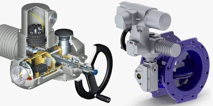
An actuator receives energy and converts it into mechanical motion. This motion is transferred to the valve through a connection between the actuator and the valve stem.
Two common forms of movement are:
- Linear movement moves the valve stem in a straight direction.
- Rotary movement turns the valve shaft through an angle.
Linear actuators are often associated with globe valves, gate valves, and certain control valves. Rotary actuators are commonly connected to ball valves, butterfly valves, and plug valves.
The required actuator movement depends on valve design. Proper alignment between the valve and actuator is important because incorrect movement can affect valve positioning and mechanical components.
Main Types of Valve Actuators
Valve actuators can be grouped according to their energy source and operating method.
| Actuator Type | Energy Source | Typical Movement | Common Application |
|---|---|---|---|
| Manual | Human force | Rotary or linear | Simple local valve control |
| Electric | Electrical power | Rotary or linear | Automated and remote systems |
| Pneumatic | Compressed air | Rotary or linear | Process control environments |
| Hydraulic | Pressurized fluid | Rotary or linear | High-force applications |
| Electro-hydraulic | Electricity and hydraulic pressure | Rotary or linear | Controlled high-force movement |
Each type has different operating characteristics. The selection process generally considers valve size, required force, operating speed, available energy, environmental conditions, and control requirements.
Why Valve Actuators Matter in Modern Systems
Supporting Consistent Flow Control
Valve actuators help maintain controlled movement of materials through piping systems. In many industrial processes, a small change in valve position can influence pressure, flow rate, or temperature.
Automated valve movement allows control systems to make repeated adjustments based on measured conditions. Sensors can detect process changes, while controllers calculate the required response and send instructions to the actuator.
This arrangement is used in water movement, heating and cooling systems, manufacturing processes, and energy facilities. The actuator acts as the physical link between a control instruction and valve movement.
Reducing Dependence on Manual Operation
Manual valves require a person to reach the valve and physically change its position. This approach can be practical for simple systems with a limited number of valves.
Complex facilities may contain many valves across wide operating areas. Some valves may also be located at height, inside enclosed equipment areas, or near high-temperature processes. Powered actuators allow many valve movements to be controlled from centralized panels or digital control systems.
Remote control does not remove the need for inspection and operational planning. It changes how valve movement is initiated and monitored.
Helping Manage Process Conditions
Valve actuators can respond to changing process conditions when connected to suitable instruments and controllers. For example, a temperature sensor may send data to a controller. The controller can then direct an actuator to adjust a valve that regulates heating or cooling fluid.
Similar control arrangements may be used for:
- Flow regulation in pipelines
- Pressure management
- Water level control
- Temperature adjustment
- Gas movement
- Steam distribution
- Process material handling
The actuator itself does not normally decide how the process should operate. It follows mechanical input or a control signal generated by another part of the system.
Supporting Protective System Functions
Some actuated valves are designed to move to a defined position when power, air pressure, or a control signal is lost. This behavior is commonly described through terms such as fail-open, fail-closed, or fail-in-place.
A fail-closed arrangement moves or returns the valve toward the closed position under defined conditions. A fail-open arrangement moves toward the open position. Fail-in-place systems are intended to remain near their last position.
The required action depends on the process and the potential consequences of interrupted operation. These arrangements are generally determined through system design and risk assessment.
Current Trends in Valve Actuator Technology
Growth of Digital Position Monitoring
Current actuator development increasingly focuses on position information and digital communication. Traditional systems may use simple open and closed signals. Newer control arrangements can provide more detailed information about valve position and actuator condition.
Digital position indicators help control systems understand whether a valve has reached the requested position. Some equipment can also record movement patterns, operating cycles, and changes in actuator behavior.
This information can support planned inspection and equipment monitoring. Data interpretation still depends on the operating environment and system design.
Integration with Industrial Automation
Valve actuators are increasingly connected with programmable logic controllers, distributed control systems, and industrial communication networks. These connections allow valve commands and operating data to move through automated control systems.
Modern control methods may use wired industrial networks or other approved communication arrangements. The exact method depends on plant architecture, equipment compatibility, and cybersecurity requirements.
Automation also allows multiple valve movements to be coordinated. A process sequence may open one valve, confirm its position, start another process step, and then adjust additional valves according to sensor readings.
Greater Attention to Energy Use
Energy management has become an important consideration in actuator design and system planning. Pneumatic systems depend on compressed air, while electric actuators use electrical energy during movement and, in some designs, while maintaining position.
Facilities increasingly examine actuator operating patterns as part of wider energy assessments. Air leakage, unnecessary valve movement, incorrect actuator sizing, and inefficient control sequences can influence overall energy use.
The current trend focuses on matching actuator characteristics with actual valve requirements rather than using the same actuator arrangement for every application.
Condition Monitoring and Data Analysis
Connected actuator systems can generate information about movement time, position changes, torque, pressure, and operating cycles. Changes in these values may indicate developing mechanical resistance or altered process conditions.
Condition monitoring does not automatically identify every equipment problem. However, operating data can provide additional information for technical review.
Between 2024 and 2026, the broader industrial trend has continued toward connected equipment, remote monitoring, and data-based maintenance planning. Valve actuator technology is part of this wider movement toward more visible and measurable industrial systems.
Rules, Standards, and Policy Considerations
Industrial Equipment and Workplace Requirements
Valve actuators are used in environments where machinery, pressure systems, electrical equipment, and process materials may be present. Their use is therefore influenced by workplace safety rules and industrial equipment requirements in the country where the facility operates.
In India, industrial workplaces may be affected by occupational safety requirements, electrical rules, environmental controls, and sector-specific requirements. Facility operators generally need to consider applicable national and state-level provisions based on the type of process.
Actuator installation may also need to account for electrical isolation, moving machinery, pressure release, and access for inspection.
Pressure and Process System Standards
Valves and actuators often form part of larger piping systems. Design requirements may refer to recognized engineering standards covering valve dimensions, pressure ratings, actuator connections, and testing methods.
Organizations such as the International Organization for Standardization and other standards bodies publish technical documents related to industrial equipment. Industry-specific codes may also apply to water, power, chemical processing, oil and gas, or building systems.
Standards do not all apply to every actuator. The relevant requirements depend on the valve type, process material, pressure level, location, and industry.
Electrical and Hazardous Area Considerations
Electric valve actuators contain powered components. Electrical installation requirements may address wiring, grounding, enclosure protection, and isolation methods.
Some industrial areas may contain flammable gases, vapors, or dust. Equipment used in these locations may need specific protection characteristics and appropriate certification for the classified area.
Pneumatic and hydraulic systems also require attention to pressure control and stored energy. Isolation procedures are important before inspection or mechanical work begins.
Environmental and Energy Policies
Environmental rules can influence the systems in which actuated valves operate. Valves may control water, air emissions, process fluids, or energy-related equipment.
Accurate valve movement can support process control, but actuator technology alone does not determine environmental compliance. The complete system, operating procedures, monitoring equipment, and facility controls all contribute to regulatory management.
Tools and Resources for Understanding Valve Actuators
Valve Sizing and Actuator Calculation Tools
Engineering calculators can help estimate valve torque, thrust, pressure difference, and actuator force requirements. These calculations are commonly based on valve type, size, fluid pressure, and mechanical characteristics.
Actuator sizing should account for the operating conditions defined for the system. A general calculator may provide an initial estimate, while detailed engineering data is used for technical design.
Technical Data Sheets
Technical data sheets contain information about actuator movement, torque or thrust, electrical characteristics, air pressure requirements, enclosure ratings, and operating limits.
When reading a data sheet, useful items include:
- Actuator type and movement
- Output torque or thrust
- Operating time
- Power or pressure requirements
- Control signal type
- Environmental rating
- Temperature range
- Position feedback method
- Mounting dimensions
Comparing these details with valve requirements helps explain how actuator and valve characteristics relate.
Valve and Actuator Selection Templates
Selection worksheets can organize basic system information before technical evaluation. A template may include valve size, valve type, pressure, temperature, movement type, required operating time, and control method.
These templates are useful for documenting system requirements. They also help identify missing information before detailed calculations begin.
Standards and Technical Websites
Websites maintained by standards organizations, government departments, and technical institutions can provide information about equipment requirements and industrial rules.
The International Organization for Standardization publishes information about international standards. Indian government portals and regulatory bodies provide access to applicable policy and workplace information. Technical engineering references can also explain valve movement, control signals, and actuator sizing concepts.
Control System Simulation Tools
Simulation platforms can model basic process behavior and control logic. Engineers and learners may use these tools to study how a valve responds to a controller signal.
A simple simulation can show the relationship between sensor readings, controller output, actuator movement, and process response. Actual industrial systems may involve additional factors such as communication delay, valve friction, pressure changes, and equipment limits.
Frequently Asked Questions About Valve Actuators
What is a valve actuator and how does it work?
A valve actuator is a device that moves a valve to control fluid or gas flow. It converts manual, electrical, pneumatic, or hydraulic energy into linear or rotary mechanical movement.
What are the main control methods used for valve actuators?
Common methods include manual control, electrical signals, compressed-air control, and hydraulic pressure. Automated systems may connect actuators with controllers, sensors, and industrial communication networks.
What is the difference between electric and pneumatic valve actuators?
Electric actuators use electrical power to create movement. Pneumatic actuators use compressed air. Their operating speed, control arrangement, energy requirements, and environmental suitability can differ.
Why is valve position feedback important?
Position feedback tells a control system where the valve is located within its movement range. This information can confirm valve movement and support process monitoring.
Can valve actuators be connected to automated control systems?
Yes. Many powered actuators can work with programmable controllers and distributed control systems when their signals and communication methods are compatible. The control system can send movement commands and receive position or condition information.
Conclusion
Valve actuators convert different forms of energy into mechanical movement that opens, closes, or adjusts valves. Manual, electric, pneumatic, and hydraulic designs support different process and control requirements. Modern actuator technology increasingly includes digital position information, automation connections, and equipment condition data. Understanding actuator operation, control methods, and system requirements provides useful general knowledge about modern fluid and process control.