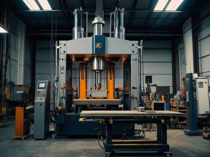
Vertical Machining Centers Guide: Explore Types, Components, Applications, Capacity, and Planning Factors
A vertical machining center is a computer-controlled machine tool designed to perform several machining operations on a workpiece from a vertical spindle orientation. A vertical machining center guide helps explain how these machines operate, the components they use, their applications, capacity considerations, and the factors involved in planning a machining process.
Vertical machining centers developed from conventional milling machines as manufacturers sought greater automation, repeatability, and flexibility. The introduction of computer numerical control, commonly called CNC, allowed machine movements to be programmed instead of being controlled entirely by hand.
In a typical vertical machining center, the spindle is positioned vertically above the workpiece. The machine can move the cutting tool and workpiece along multiple axes, depending on its configuration. A basic three-axis system generally provides movement along the X, Y, and Z axes, while more advanced machines may incorporate additional rotary axes.
How a Vertical Machining Center Works
The machining process begins with a digital part program containing instructions for tool movement, spindle operation, cutting parameters, and other machine functions. The controller interprets these instructions and directs the machine's motors and mechanical systems.
The cutting tool is held in a spindle and brought into contact with the workpiece. Material is removed through controlled cutting action. Depending on the machine and program, operations can include milling, drilling, tapping, boring, reaming, and related processes.
Main Types of Vertical Machining Centers
Vertical machining centers can be grouped according to their configuration and intended application. Common categories include:
- 3-axis vertical machining centers: Provide X, Y, and Z movement and are widely used for straightforward prismatic components.
- 4-axis vertical machining centers: Add a rotary axis that allows the workpiece to be positioned from another direction.
- 5-axis vertical machining centers: Provide additional rotary movement and can machine multiple surfaces or complex geometries with fewer setups.
- High-speed vertical machining centers: Designed around higher spindle speeds and rapid machine movement for suitable materials and applications.
- Heavy-duty vertical machining centers: Built with structures and drive systems intended for demanding cutting conditions.
- Compact vertical machining centers: Designed around smaller workpieces and limited floor space.
The exact classification can vary among manufacturers and machine specifications, so capacity should be evaluated using the individual machine's technical documentation.
Importance
Vertical machining centers are important because they combine several machining operations within one computer-controlled platform. This can reduce the number of separate machines or manual setups needed for certain components and can make repeated production processes easier to organize.
These machines are used in industries such as automotive manufacturing, aerospace, electronics, medical equipment production, energy equipment, tooling, mold making, and general engineering.
Applications of Vertical Machining Centers
A vertical machining center can be used for many operations, including:
- Face milling
- End milling
- Slot and pocket machining
- Drilling
- Tapping
- Boring
- Reaming
- Contouring
- Mold and die machining
- Prototype component production
The appropriate operation depends on the material, geometry, tolerance requirements, cutting tools, machine capability, and production method.
Capacity Considerations
Machine capacity is not represented by a single number. Several specifications determine whether a vertical machining center can accommodate a particular component.
| Capacity factor | What it indicates |
|---|---|
| Table size | Available workholding area |
| Maximum workpiece weight | Load that the table and machine structure can support |
| X-axis travel | Horizontal movement range in one direction |
| Y-axis travel | Horizontal movement range in the second direction |
| Z-axis travel | Vertical machining range |
| Spindle speed | Available rotational speed range |
| Spindle power | Available power for cutting operations |
| Tool capacity | Number of tools the automatic tool changer can hold |
| Machine envelope | Physical space occupied by the machine |
| Workpiece clearance | Space available around the tool and component |
A workpiece should fit within the machine's actual travel limits while also allowing space for fixtures, tools, clamps, and safe tool movement.
Factors Affecting Machining Capacity
The practical capacity of a machine also depends on material hardness, cutting-tool geometry, spindle characteristics, rigidity, coolant arrangements, fixture design, and the complexity of the machining operation.
For example, a machine may have sufficient table dimensions for a large component but still be unsuitable if the workpiece exceeds its weight limit or requires more Z-axis clearance than the machine provides.
Recent Updates
From 2024 through 2026, vertical machining center development has continued to reflect broader trends in CNC manufacturing, including automation, digital monitoring, improved controls, energy management, and integration with factory software.
One notable direction is the increased use of machine monitoring. Sensors and control systems can collect information about spindle conditions, vibration, temperature, machine utilization, and other operating parameters. This information can support process analysis and production planning.
Automation is another significant development. Vertical machining centers can be integrated with robotic loading systems, pallet systems, automatic tool management, probing equipment, and production monitoring platforms. These systems can reduce manual handling between machining operations when the production environment is designed for automation.
CNC Control Developments
Modern CNC controls increasingly integrate graphical interfaces, toolpath visualization, machining simulation, data collection, and diagnostic functions. These capabilities can help operators understand programmed operations and identify potential issues before or during machining.
Some systems also support connectivity with manufacturing execution systems and other digital production platforms. The level of connectivity depends on the machine controller, software, factory network, and integration architecture.
Automation and In-Process Measurement
Touch probes and tool measurement systems can be integrated into many vertical machining centers. A workpiece probe can help establish workpiece position, while tool measurement systems can detect tool dimensions or changes.
These technologies are particularly relevant where repeated machining operations require consistent positioning. Their usefulness depends on the specific production process and measurement requirements.
Laws or Policies
In India, the operation of CNC machinery in industrial workplaces is influenced by occupational safety requirements, electrical safety provisions, machinery safeguards, and applicable state or central regulations.
The Occupational Safety, Health and Working Conditions Code, 2020 provides a broad legal framework concerning occupational safety, health, and working conditions. Its requirements cover areas such as employer responsibilities, workplace safety, welfare facilities, and occupational conditions.
The Factories Act framework and applicable rules have also historically addressed machinery guarding, worker safety, training, and safe operating practices. The exact legal requirements depend on the applicable legislation, implementation status, state rules, workplace type, and industrial activity.
Relevant Indian Standards may also provide technical references for machine tools, CNC equipment, electrical safety, guarding, and related equipment. Standards should be checked according to the specific machine and application rather than assumed to apply universally.
Workplace Safety Considerations
Safe operation of a vertical machining center generally involves:
- Keeping machine guards and doors properly positioned.
- Following the machine manufacturer's operating instructions.
- Checking workholding arrangements before machining.
- Confirming that cutting tools are correctly installed.
- Maintaining appropriate spindle and tool operating limits.
- Managing chips and coolant safely.
- Using appropriate personal protective equipment.
- Keeping unauthorized personnel away from hazardous operating areas.
- Following established emergency-stop and shutdown procedures.
Safety requirements should be based on the machine documentation and applicable workplace regulations.
Tools and Resources
Several technical resources can help users understand, evaluate, or plan work involving vertical machining centers.
Machine Specification Sheets
Machine specification sheets provide information such as axis travels, table dimensions, spindle characteristics, tool capacity, machine weight, and maximum workpiece dimensions. These specifications are useful when determining whether a machine can accommodate a planned component.
CNC Programming Resources
CNC programming references explain coordinate systems, G-code, M-code, tool offsets, work offsets, canned cycles, and machining operations. Programming conventions can differ between CNC controls, so the relevant controller documentation should be consulted.
Cutting Parameter Calculators
Machining calculators can help estimate spindle speed, feed rate, cutting speed, and material-removal conditions. Typical inputs include tool diameter, number of cutting edges, material, and target cutting conditions.
The calculated values are starting points rather than universal operating requirements. Machine rigidity, tool geometry, workholding, coolant, and manufacturer specifications must also be considered.
CAD/CAM Software
CAD/CAM platforms are commonly used to create part geometry and generate CNC toolpaths. CAM software can simulate tool movement and help identify potential collisions or machining issues before a program reaches the machine.
Planning Checklist
A basic planning process can consider:
- Workpiece dimensions and weight
- Material and hardness
- Required machining operations
- Number of axes needed
- Table and fixture requirements
- Spindle speed and power
- Tool diameter and tool length
- Tool changer capacity
- Coolant requirements
- Tolerance and surface requirements
- Production quantity
- Inspection and measurement needs
- Available floor space and utilities
FAQs
What is a vertical machining center?
A vertical machining center is a CNC machine tool with a vertically oriented spindle. It can perform multiple cutting operations, including milling, drilling, tapping, boring, and reaming, depending on its configuration.
What are the main components of a vertical machining center?
Major components generally include the machine bed, column, table, spindle, spindle motor, CNC controller, axis drives, guideways, ball screws or other motion systems, automatic tool changer, workholding equipment, and coolant system.
What is the capacity of a vertical machining center?
The capacity depends on specifications such as table size, X-Y-Z axis travel, maximum workpiece weight, spindle power, spindle speed, tool capacity, and available clearance. There is no single capacity value that applies to all vertical machining centers.
What are vertical machining centers used for?
Vertical machining centers are used for operations such as milling, drilling, tapping, boring, pocketing, contouring, and mold or tooling work. Their applications range from prototype machining to repeated industrial production.
How do you plan work for a vertical machining center?
Planning normally begins by assessing the workpiece material, dimensions, weight, geometry, tolerances, required operations, tooling, workholding, machine travels, spindle requirements, and production quantity. These factors help determine whether the machine configuration is appropriate for the planned process.
Conclusion
Vertical machining centers are CNC machine tools that use a vertically oriented spindle to perform a range of controlled machining operations. Their capabilities depend on factors such as axis travel, table dimensions, spindle characteristics, tooling, workholding, and machine rigidity. Recent developments have increased the integration of automation, monitoring, probing, and digital manufacturing systems. Understanding machine capacity and planning requirements helps clarify how a particular vertical machining center can be applied to different machining tasks.